

- Model: Gas interlock kit
- Weight: 0.10kg
- Dimensions: 250.00mm x 199.00mm x 216.00mm
This offer ends in:
Available Options
Gas Interlock System – New Design 2025
Overview The Gas Interlock System – New Design 2025 ensures gas safety compliance for commercial kitchens and industrial environments. Designed for versatility, compactness, and ease of installation, it delivers reliable performance and meets BS6173 and CE standards.
Key Features
Monitors 1 or 2 fans up to 15A.
In-built sensors ensure compliance with BS6173 standards.
Compact design (85 x 48 x 134 mm) fits easily into small spaces.
Wide control range (0.25 to 15A) supports most fan sizes.
Simple installation and commissioning process.
Cost-effective alternative.
Fully compliant with CE and BS6173 regulations.
Advanced Monitoring and Controls
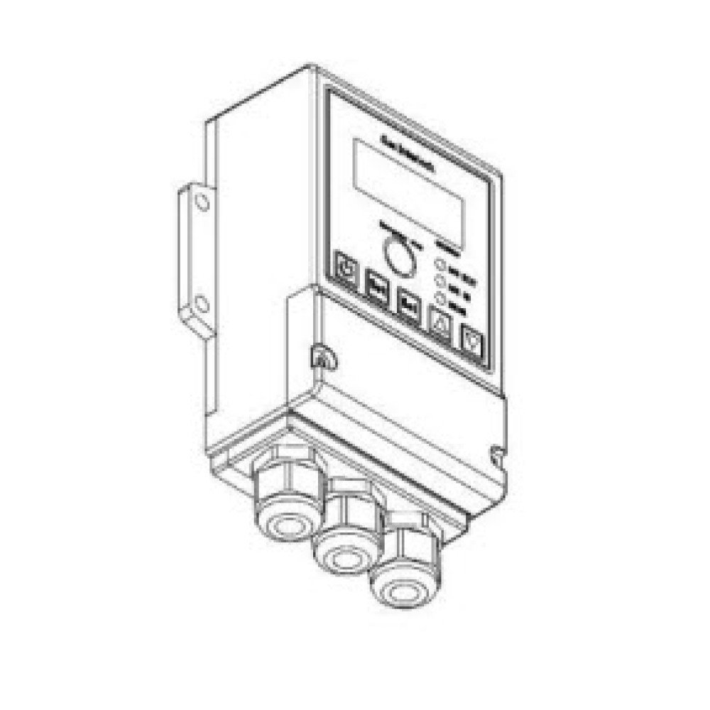
Digital LED Display for clear monitoring.
Current Sensing up to 15A to detect fan operation.
Commissioning Access Button for simplified setup.
Emergency Stop Button for immediate shut-off.
Simplified wiring reduces installation time.
Suitable for category B appliances like combi-ovens, grills, griddles, and fryers.
Why Choose Our Gas Interlock Panel?
Versatile Design – Suitable for both large and small installations.
Compact Size – Ideal for tight areas with space-saving dimensions.
Flexible Control Range – Handles most fan sizes with a 0.25 to 15A range.
Ease of Use – Quick installation and commissioning process.
Affordable Pricing – Provides excellent value compared to competitors.
Reliable Compliance – Fully meets BS6173 requirements.
Applications
Suitable for appliances using natural gas or LPG in hotels, restaurants, takeaway outlets, and mobile catering units.
Required when power-operated flue systems are installed in commercial kitchens.
Mandatory for new ventilation or extraction systems.
Necessary for new gas-line pipework or kitchen layouts.
Ideal for category B appliances like combi-ovens, grills, griddles, and fryers.
Understanding Gas Interlock Systems A gas interlock system, also known as a gas safety interlock system, prevents hazardous gas leaks and ensures appliances are operated safely. These systems are essential in commercial kitchens, laboratories, and industrial environments.
Key Functions:
Current Sensors – Monitor fan motor currents to detect speed changes.
Control Panel – Processes sensor data to manage gas supply.
Set Point Adjustment – Sets minimum fan speed levels. Alarms and shut-offs trigger if thresholds are breached.
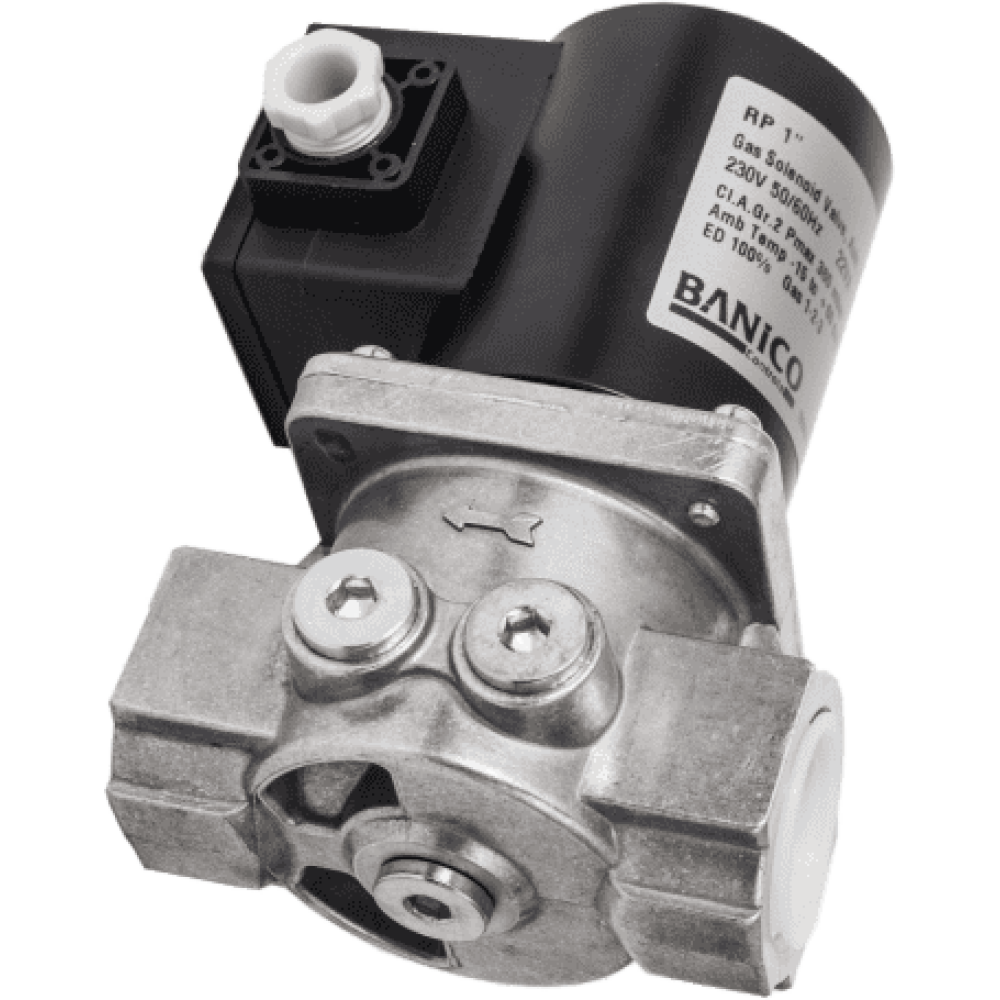
Automatic Shut-Off Valves – Cuts off gas supply during hazardous conditions using solenoid valves.
Alarms and Indicators – Provides audible and visual alerts for emergencies.
Safety Benefits Gas interlock systems help prevent accidents, fires, and harmful gas exposure. Compliance with regulations is guaranteed when installed and maintained by qualified professionals.
Complete Kit Availability We supply complementary components, including:
Gas solenoid valves.
Fan speed controllers.
Inverters.
Emergency stop buttons.
These components work together to create a fully integrated safety system.
Installation Guidelines
Installation must be performed by a qualified Electrical Engineer.
Place the unit in a clean, dry location, away from excess heat (above 50°C).
Install in an accessible area or provide additional emergency stop buttons.
System Components and Setup Gas interlock systems integrate seamlessly with canopy fans, solenoid valves, and fan speed controllers. Ventilation engineers can size the correct valve and controller ratings for optimal performance.
Wiring Instructions
Single-Phase Wiring:
Connect L1 from terminals 6 & 7 to speed controller(s).
Follow standard configurations for remaining connections.
Three-Phase Wiring:
L1 connects from terminals 6 & 7 to the speed controllers.
L2 and L3 connect directly to the speed controllers.
Mirror single-phase setups for other connections.
System Indicators
Extract Fan: Displays normal or error status with a 10-second alarm delay.
Inlet Fan: Displays normal or error status with a 10-second alarm delay.
Valve Status: Indicates whether the valve is OPEN or CLOSED.
Button Operations
Red Power Button: Starts/stops operation and exits parameter settings.
SET Button: Enters current sensor settings.
SEL Button: Selects the desired current sensor for adjustments.
UP/DOWN Buttons: Adjusts trigger points for sensors.
EMERGENCY STOP Button: Closes the gas valve immediately and triggers an audible alarm.
Error Messages and Troubleshooting
Error Extract Fan or Error Inlet Fan:
Fan speed below trigger point. Adjust fan speed or sensor settings.
Emergency Stop:
Solenoid valve closed due to emergency button press. Reset and restart.
Setup Instructions
Enter Startup Mode (press ON/OFF button if required).
Long-press SET and SEL for 3 seconds to access settings.
Use SET to select extract or inlet fan.
Turn sensors ON or OFF using UP/DOWN buttons.
Adjust sensor trigger points to 10% below fan speed set point.
Exit setup with the ON/OFF button and start the system.
Wiring Connections
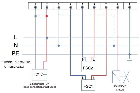
Live 240VAC Supply: Terminal 2
Neutral 240VAC Supply: Terminal 3
Earth: Terminal 9
Emergency Stop Button: Terminals 1 & 2 (loop connection if not used)
Fan Speed Controller 1: Live to 4 and Neutral to 7
Fan Speed Controller 2: Live to 5 and Neutral to 6
Solenoid Valve: Live to 8 and Neutral to 3
Conclusion Our gas interlock systems provide reliable, cost-effective, and compact solutions for gas safety compliance. Ideal for commercial kitchens and industrial environments, they ensure maximum safety, easy installation, and full compatibility with various components. Explore our full range of products online and equip your site with the best-in-class gas interlock systems.
| ELECTRICAL | |
| Voltage | 240 V AC |
| Amps | 1.55 Amps |
| Watts | 355 |
| Poles | 2 Pole 1850 rpm |
| TECHNICAL | |
| Dimensions | 220mm x 199 mm x 216mm |
| Sound Pressure Level (dBA) | 63dB(A) |

